Technical starting point
Die dimensions, pad map, I/O requirements, power dissipation and board constraints.

ASSEMBLY AND PACKAGING
Evaluate package interfaces, interconnect requirements and thermal/mechanical constraints before assembly release.
Discuss your requirements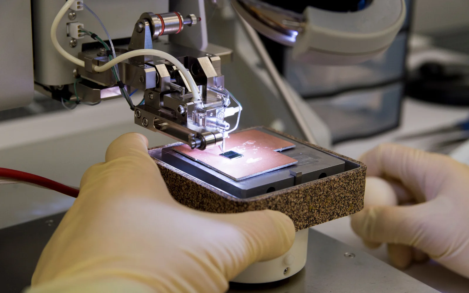
Representative photograph · Technician operating a semiconductor wire-bonding machine.
THE ENGINEERING SCOPE
Die dimensions, pad map, I/O requirements, power dissipation and board constraints.
Bond or bump connectivity, package parasitics, thermal assumptions and manufacturability review.
Package requirements, pin maps, interface notes and supplier review actions.
CLIENT GUIDE
Use these technical checkpoints to make the first project review productive.
HOW WE WORK
The initial review establishes the baseline using die dimensions, pad map, I/O requirements, power dissipation and board constraints. Record gaps and dependencies before implementation.
Carry out the agreed work against the reviewed baseline. For assembly and packaging, keep the interfaces and configuration used by this stage visible to the receiving team.
Retain the intermediate artifacts and review bond or bump connectivity, package parasitics, thermal assumptions and manufacturability review. Investigate failures before using these results as an input to the next stage.
Package package requirements, pin maps, interface notes and supplier review actions. Review unresolved findings against the agreed acceptance criteria and assign ownership for follow-up.
PROJECT DECISIONS
Use these gates to agree readiness, review evidence and responsibility at each stage.
Are the starting inputs complete enough to proceed?
Die dimensions, pad map, I/O requirements, power dissipation and board constraints.
Record input revisions, missing material and who can resolve each dependency.
Has the work addressed the agreed technical objective?
Evaluate package interfaces, interconnect requirements and thermal/mechanical constraints before assembly release.
Keep the intermediate artifacts with review comments and the decisions that changed the design.
Can the result be reproduced and interpreted?
Bond or bump connectivity, package parasitics, thermal assumptions and manufacturability review.
Capture the configuration, expected result, observed result and unresolved findings.
Can the receiving team use the delivery package?
Package requirements, pin maps, interface notes and supplier review actions.
Review build or execution instructions, known limitations and ownership of follow-up actions.
INPUTS & OUTPUTS
The final statement of work defines the scope and acceptance criteria.
TECHNICAL DECISIONS
Evaluate package interfaces, interconnect requirements and thermal/mechanical constraints before assembly release.
The work starts from die dimensions, pad map, I/O requirements, power dissipation and board constraints. The team should identify the authoritative revision of each input and record any assumptions needed to proceed. This prevents a later result from being interpreted against a different specification or configuration.
Package choices affect both signal behaviour and heat removal; supplier capability and qualification must be confirmed for the selected construction.
The review centres on bond or bump connectivity, package parasitics, thermal assumptions and manufacturability review. Each finding should identify the input revision, observed behaviour and supporting evidence. Distinguish a confirmed defect from a configuration issue, an unsupported case or an open engineering question before deciding how to resolve it.
The practical sequence is: compare package options; review interconnect and pinout; assess electrical/thermal interfaces; coordinate assembly collateral. Intermediate reviews allow the client to resolve decisions while changes are still manageable. If an input changes, identify the affected activities and repeat the checks that depend on it.
The expected package comprises package requirements, pin maps, interface notes and supplier review actions. Acceptance criteria should specify what the receiving team needs to reproduce, inspect or integrate these artifacts. Include known limitations and outstanding actions in that package, rather than assuming that delivery of a file implies acceptance.
Test and manufacturing-support work relies on traceable device, board and measurement information. Keep sample identity, lot or revision, fixture version, instrument settings and environmental conditions with the results. Establish how limits are chosen and which reference measurements support them. A result without these conditions can be difficult to compare after a fixture, device or software change.
Correlation should precede optimisation. Compare repeated measurements, investigate setup sensitivity and distinguish contact or fixture failures from device behaviour. When looking at yield, segment data by the relevant conditions instead of treating an aggregate trend as a root-cause finding. Changes to test order, settling time or limits can affect the distribution and must be recorded.
Coordinate release requirements with the actual assembly, test or fabrication partner. Confirm the format and ownership of interface files, test programs and acceptance records. Design engineering support does not imply ownership of a manufacturing line, procurement responsibility or qualification authority. Destructive analysis, stress testing and sample consumption need a defined sequence and approval boundary within the project plan.
A device appears to fail only on one fixture. Repeat the measurement under controlled conditions, compare contacts and calibration, and use a known-good reference where available. Preserve the original failing data before changing the setup. The aim is to distinguish device failure from the measurement chain; this illustration does not establish a diagnosis for an actual sample.
BEFORE WE BEGIN
A clear conversation is the start of a strong engineering relationship.
The starting review needs die dimensions, pad map, I/O requirements, power dissipation and board constraints. Share the current revision and known limitations so the scope reflects the actual design state.
The statement of work can define package requirements, pin maps, interface notes and supplier review actions. The final package should include review results and any open actions.
Package choices affect both signal behaviour and heat removal; supplier capability and qualification must be confirmed for the selected construction.
The first work package can be a review of the available inputs and the engineering questions that must be resolved. Agree its boundaries, access requirements and expected findings before committing to a larger implementation. A review should leave an actionable list of decisions, dependencies and next steps.
Tie each finding to the relevant revision and supporting evidence. A change should identify the affected interfaces, activities and checks. Confirm its effect on scope and delivery with the responsible owner. At handoff, distinguish closed findings, accepted limitations and open work so that a file transfer is not mistaken for technical acceptance.
PUT THE WORKFLOW IN CONTEXT
Practical reading to help prepare your project discussion. Studies are illustrative; they do not report client results.
Connecting DFT deliverables to manufacturing test ↗YOUR NEXT CHAPTER STARTS HERE
Bring us your engineering challenge.
Let’s define the path from idea to implementation.